CNC Coordinate System Made Easy
2020-01-17CNC Coordinate System Made Easy
The CNC Coordinate System Made Easy for New Machinists
You’ll use your coordinate system fundamentals everywhere, not just for one particular CNC machine. Even the latest machines are the same at their core: they use an X, Y, and Z axis to define the coordinate space inside the machine, and a tool (sometimes an endmill, sometimes an extruder, sometimes a laser beam) moves around that space. The technology might change, but the fundamentals remain essentially the same. In this article we’ll be covering the basics of the CNC coordinate system including the Cartesian coordinate system, work coordinate system (WCS), and offsets.
Why Do Coordinates Matter?
Additive machines build a part from the bottom up. There’s no question about where the piece starts on the build plate. However, something like a milling machine has to subtract material away from an external object. To do this, the machine needs to understand the position of the stock in physical space. If only it was as simple as shoving a block of metal into your CNC and pressing go.
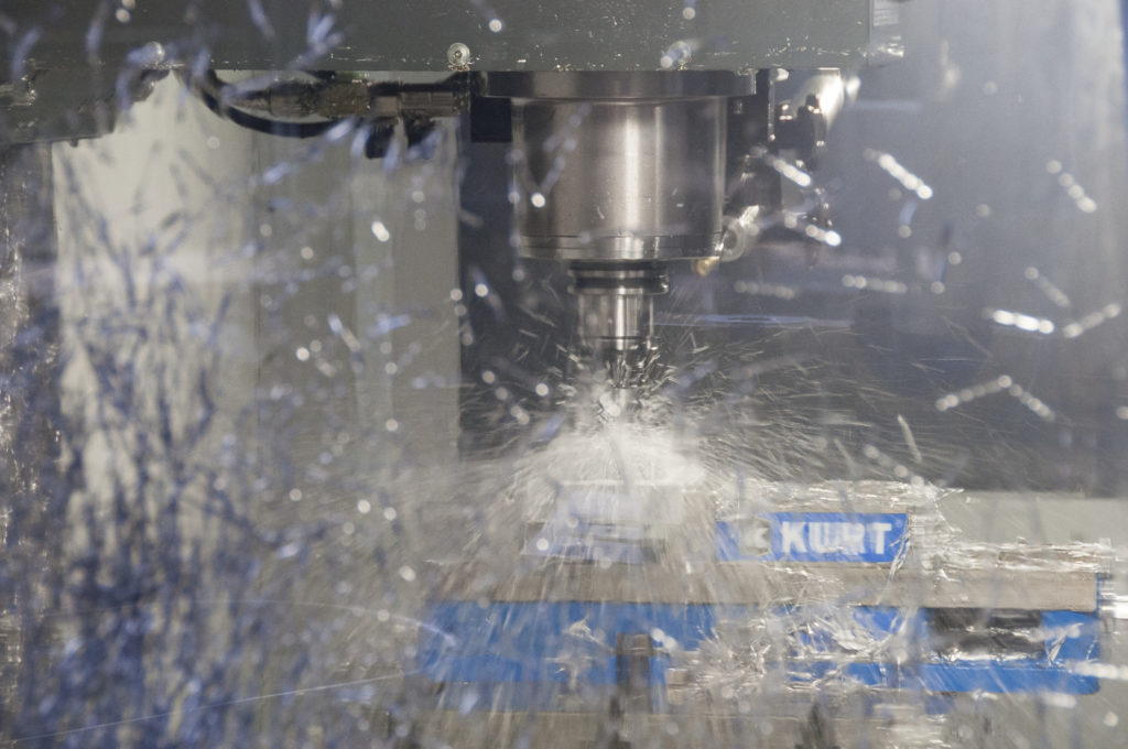
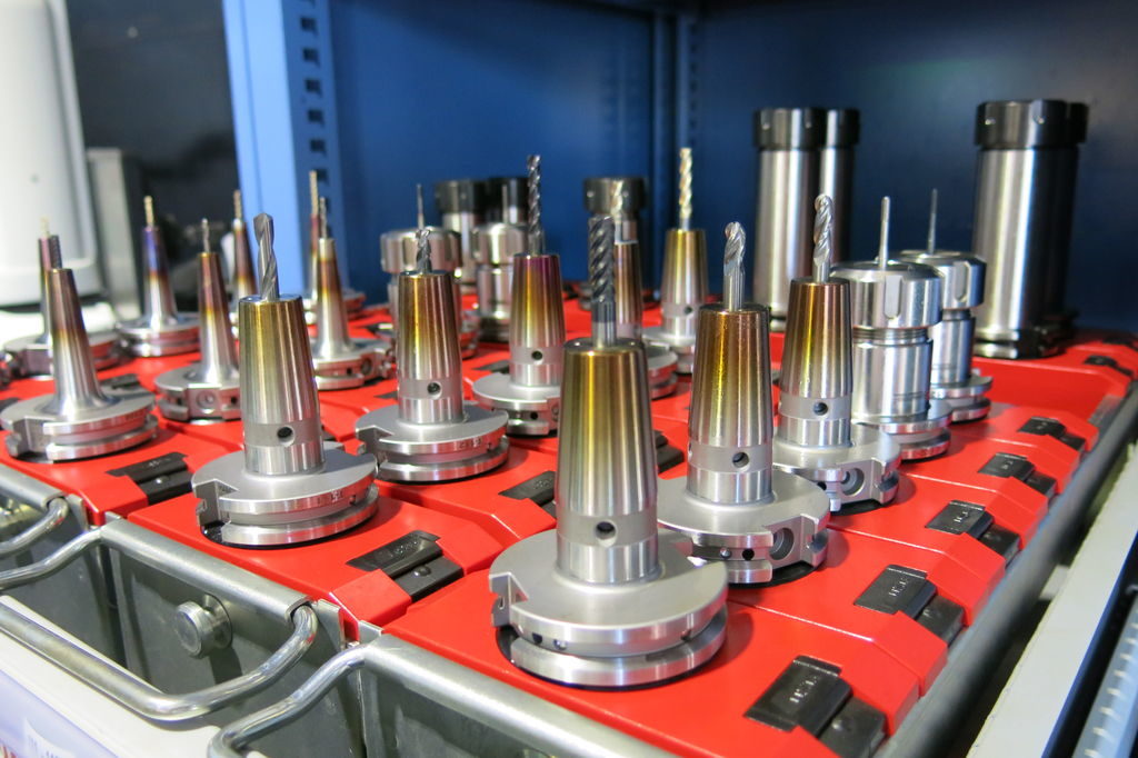
Things start to get complicated when you add in a variety of milling tools. Each bit has a different length which changes the distance between the spindle datum and the workpiece. That origin point you just set for a 1″ long endmill isn’t going to work for a 3″ long drill.
You can think of the coordinate system as how CNC machines understand 3D space. Without a coordinate system, your CNC would have absolutely no way of knowing:
Where your block of material is
How far away your tool is from your part
What movements to use to machine your part
The coordinate system might seem complicated at a glance, but it can be broken down into simple components. Let’s first start with the basics of the Cartesian coordinate system.
Cartesian Fundamentals
Nearly all CNC machine uses a Cartesian coordinate system based on an X, Y, and Z axis. This system allows a machine to move in a specific direction along a specific plane.
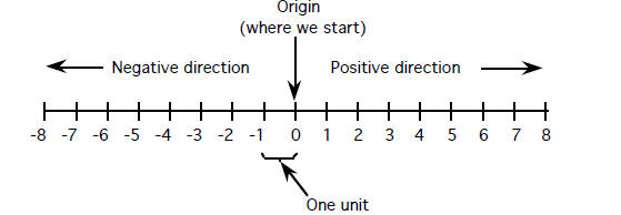
Reduce the Cartesian system to its basics and you have a familiar number line. One point on the line gets designated as the Origin. Any numbers to the left of the Origin are negative, numbers to the right are positive.
Combine the X, Y, and Z axes together at 90 degree angles and you create a three dimensional space for your CNC machine to move around in. Each axis meets at the Origin.
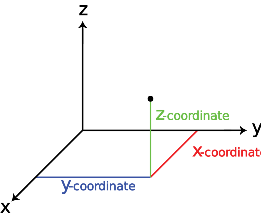
When two axes connect together you form what’s called a Plane. For example, when the X and Y axes meet you get an XY plane, which is where your most of the work happens on 2.5D parts. These planes are divided into four quadrants, numbered 1-4, which have their own positive and negative values.

An easy way to understand the Cartesian coordinate system in relation to your CNC machine is using the Right Hand Rule. Hold your hand out palm up with your thumb and index finger pointed outwards, and your middle finger pointed upwards. Place your hand in front of your CNC machine, aligned with the machine’s spindle and you’ll see the axes line up perfectly.
Middle finger is the Z axis.
Index finger is the Y axis.
Thumb is the X axis.

How a CNC Machine Uses Coordinates
Using the Cartesian coordinate system, a CNC machine can be controlled along each axis to transform a block of material into a finished part. Although it’s difficult to describe axes using relative terms, based on each axis, you typically get the following movements from the perspective of an operator facing the machine:
X axis allows movement “left” and “right”
Y axis allows movement “forward” and “backward”
Z axis allows movement “up” and “down”
Put all of this together, and you have a machine that can cut not only various sides of a workpiece in the XY plane, but also at various depths along the Z axis. Whether it’s a milling machine, router, or laser, they all use this fundamental movement system.
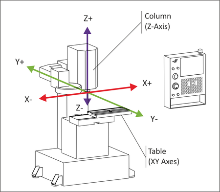
The movement of your CNC along the coordinate system is always based on how your tool moves, not the table. For example, increasing the X coordinate value would move the table left, but when looked at from the perspective of the tool, it’s moving right along a workpiece.
Increasing the Z axis coordinate would move the spindle up, decreasing it would move it down into a workpiece. You are cutting into the piece which corresponds to a negative Z axis coordinate.
If reading that left you more confused than before, don’t worry. Understanding the difference between the movement of your tool and table is easier to show than explain with words. Check out the video below from Robert Cowan to see this in action:
Your CNC Machine’s Origin
Every CNC machine has its own internal origin point called Machine Home. When your CNC first boots up, it has no idea where it is in physical space and requires a calibration to get its bearings.
When this process occurs, all three axes of your CNC move towards their maximum mechanical limit. Once a limit is reached, a signal gets sent to a controller which records the home position for that particular axis. When this occurs for all three axes, the machine is now “homed.”
Under the hood, the process can vary from machine to machine. For some machines there is a physical limit switch that signals the controller that a machine has reached an axis limit. On some machines there’s an entire servo system in place that makes this entire process incredibly fluid and precise. A machine controller sends a signal through a circuit board to a servo motor, which connects to each machine axis. The servo motor rotates a ball screw that’s attached to the table on your CNC machine, making it move.
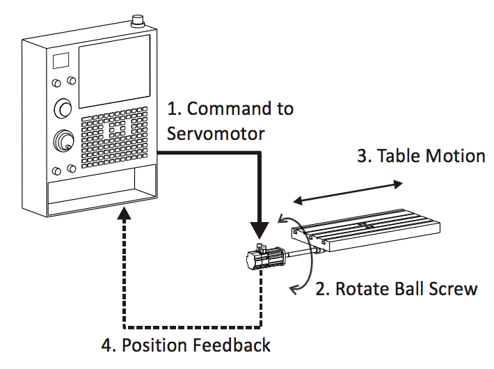
The back and forth movement of the table communicates coordinate changes instantaneously within accuracies up to .0002 inches.
How Machinists Use Coordinates
So far we’ve talked about how a CNC machine uses its internal coordinate system. The problem is, this coordinate system isn’t very easy to reference by us humans. For example, when your CNC finds its home position, it’s typically at extreme mechanical limitations along the X, Y, and Z axes. Imagine having to use these extreme coordinate values as the starting place for your CNC program. What a nightmare.
To make writing CNC programs easier, we use a different coordinate system designed for human manipulation called a Work Coordinate System, or WCS. The WCS defines a particular origin point on a block of material, usually in CAM software like Fusion 360.

You can define any point on a block of material as the origin point for a WCS. Once an origin point is established, you will need to locate it inside your CNC machine using an edge finder, dial indicator, probe, or some other locating method.
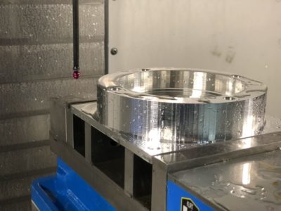
Choosing an origin point for your WCS requires some careful planning. Keep these points in mind when going through the process:
The origin will need to be found by mechanical means with an edge finder or probe
Repeatable origins help save time when swapping out parts
The origin needs to account for required tolerances of downstream operations
There could be another full blog on selecting the most optimal origin point, especially for each subsequent setup as the tolerance stack up begins to grow. Make sure you keep in mind the tolerances of previously machined features, your locating mechanism, and your machine to ensure your final part is to spec.
How CNC and Human Coordinates Interact
As we mentioned above, human operators will use a WCS which provides an easy set of coordinates for writing a CNC program. However, these coordinates are always different from a machine’s coordinates, so how does your CNC machine line the two up? With offsets.
A CNC machine will use what’s called a work offset to determine the difference in distance between your WCS and its own home position. These offsets get stored in the controller of the machine, and can typically be accessed in an offset table like the one below.
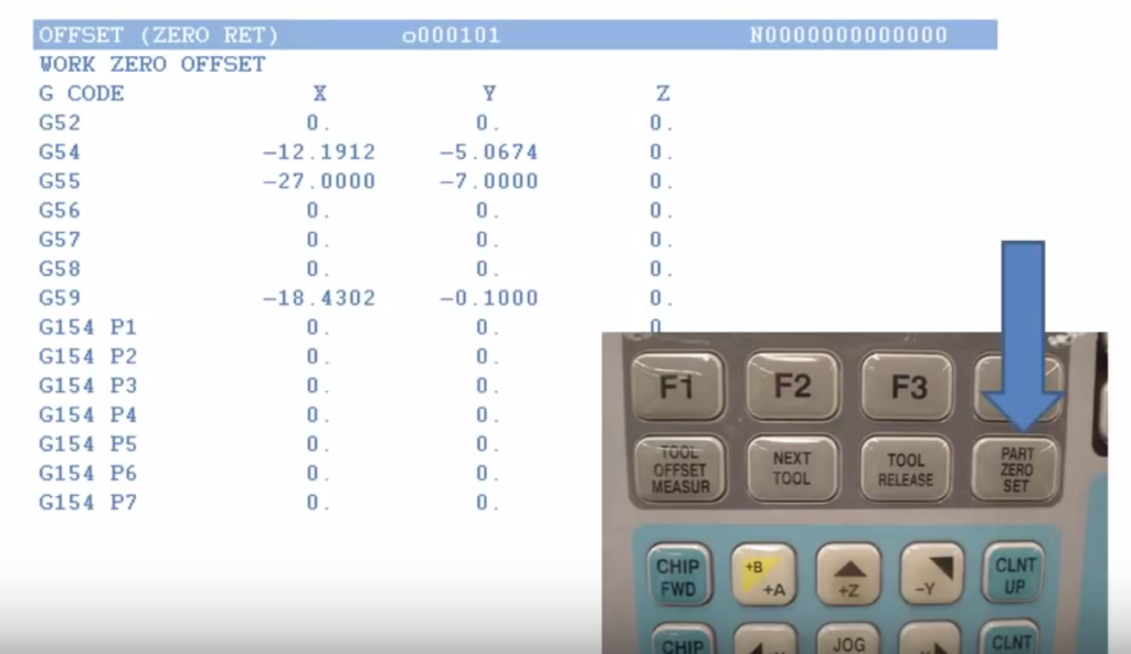
Image courtesy of etprof on YouTube.
Here we can see that several offsets have already been programmed, G54, G55, and G59. What’s the benefit in having multiple offsets? If you are machining multiple parts in one job, each part can be assigned its own offset. This allows the CNC machine to accurately relate its coordinate system to multiple parts in different places, and complete multiple setups at once.
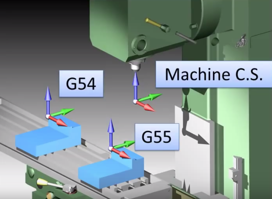
Image courtesy of etprof.
Tool Offsets
It’s pretty common to use multiple tools for the same job, but you need a way to account for different tool lengths. A tool offset are programmed into your CNC machine to make this easy work. With a tool offset programmed, your CNC machine will know exactly how far each tool extends from the spindle. There are several ways to record a tool offset:
Jogging. Move the tool from the machine’s home position to the part’s zero position. The distance traveled is measured and entered as the tool’s offset.
Precision block. Set all tools to a common Z position at the top of a 1-2-3 precision block that rests on the machine’s table.
Probing. Use a probe to automatically determine the tool offset. This is the most efficient method but also the most expensive, as it requires the probe equipment.
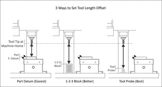
Image courtesy of Practical Machinist.
Putting it All Together
Now that we have all our coordinate fundamentals in place let’s walk through a set of sample jobs. We’re using a part that was already manually machined to define an outside shape. Now we need to use a CNC machine to drill some holes, pockets, and a slot.
Job 1
We first need to secure and establish our axes and origin point:
The part is clamped in a vise, which is bolted to our machine table, and was squared to the machine axes.
This keeps the WCS X-axis aligned with the machine’s X-axis.
The left part of the face sits against a Vise Stop. This establishes a repeatable X-axis origin.
Since one of the vice jaws is fixed, we can use this jaw to determine a repeatable Y-axis origin, finding this location with the help of an edge finder or probe.
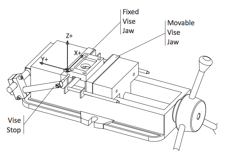
With our WCS in place, our machine now understands the stock position relative to its own internal coordinates. The machining process begins with machining the pocket and drilling holes on the first side of the part.
Job 2
Now the part has to be flipped over to work on the other side. Since we just flipped the part 180 degrees, the outer contour was symmetric, and the previous X and Y offsets were repeatable, the WCS will not change. We are also using the same tool, so the same Z offset can be used.
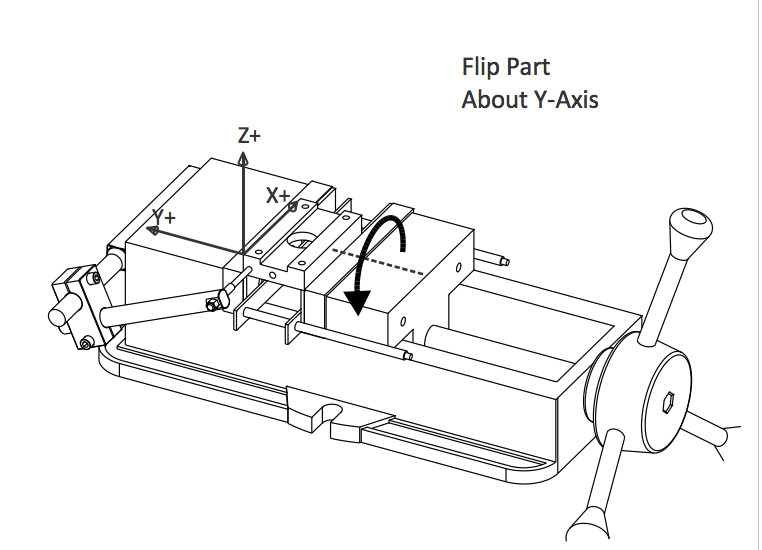
One important variable to keep in mind here is the clamping force of your vice. If you haven’t already seen it in your shop, machinists will typically mark the closed position of a vice with a black marker or use a torque wrench. Why are they doing this? To create a consistent clamping pressure when moving or rotating parts. Changes in clamping pressure can lead to differences in the positioning of a part, or other failures like part deformation or bowing depending on part geometry. Assuming that our clamping force is more or less the same, Job 2 can now be machined.
Job 3
Now we need to drill some holes, which requires standing the part on its end. This rotation doesn’t change the XY-origin of the WCS. However, we now have a shorter travel distance between our tool and part.
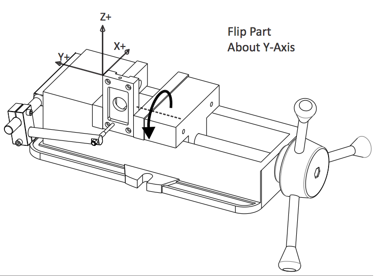
This requires a new offset to be used, which will shift the origin point to the top corner of the part. We also removed the parallels to increase gripping surface and lowered the Vice Stop so it connects with the face of the part instead of the bottom pocket.
We can still use two of our original reference planes here to complete Job 3.
This is a really simple example; the part is square, the XY origin was repeatable for all three setups, and even the Z origin only changed once. But the thought process of workholding alignment, repeatability, and accuracy of previous features is important and you’ll find yourself going through those basic steps again and again.
Locked and Loaded
You’ve now got the precision of CNC coordinate knowledge in your Machinist tool belt, use it wherever your career takes you! Work Coordinate Systems (WCS) bridge the gap between the internal machine coordinates and your CNC program. These three systems work together to precisely locate and machine parts with consistent quality time and time again. Whether you’re rocking a Bridgeport, Tormach, or Haas, the coordinate system always stays true.


